Technology Transfer Network
Emission Measurement Center Spectral Database
Fourier Transform Infared (FTIR) Method Validation at a Coal Fired Boiler
|
EPA Document No. 454R95004
EPA Contract No. 68D20163 Work Assignment No. 2 JULY 1993 Prepared by: Research Division Entropy Environmentalists, Inc. Post Office Box 12291 Research Triangle Park, North Carolina 27709 Prepared for: Lori T. Lay U.S. Environmental Protection Agency Emissions Measurement Branch Research Triangle Park, North Carolina 27711
DISCLAIMER This document was prepared by Entropy Environmentalists, Inc. under EPA Contract No. 68D20163, Work Assignment No. 2. This document has not been reviewed by the U.S. Environmental Protection Agency. The opinions, conclusions, and recommendations expressed herein are those of the authors, and do not necessarily represent those of the United States Environmental Protection Agency. Mention of specific trade names or products within this report does not constitute endorsement by the EPA or Entropy Environmentalists, Inc. TABLE OF CONTENTS
2.0 PROCESS DESCRIPTION AND SAMPLE POINT LOCATIONS
1.0 INTRODUCTION1.1 BACKGROUNDThis report describes results of the Fourier transform infrared (FTIR) method field validation test that was conducted at a coal-fired boiler facility. The validation test was conducted from January 25 to February 10, 1993 by Dr. Grant M. Plummer, Mr. Scott A. Shanklin, Mr. Greg C. Blanschan, Dr. Thomas A. Dunder, Dr. Thomas J. Geyer, Ms. Lisa M. Grosshandler, Dr. Ed Potts, Ms. Patricia Royals, Mr. Rick Strausbaugh, and Mr. Mike Worthy, of Entropy Environmentalists, Inc., under U.S. EPA Contract No. 68D20163, Work Assignment No. 2. FTIR spectrometry is of interest in emissions testing because of its usefulness in performing multicomponent gas analyses. Because each distinct molecular structure possesses a distinct infrared absorption spectrum, FTIR instruments can provide quantitative and qualitative information on the composition of sample gases. This aspect of the technique, along with its potential for providing near-real-time analytical results, is particularly important considering the number of hazardous air pollutant (HAP) compounds listed in the Clean Air Act Amendment of 1990. FTIR-related tasks previously performed by Entropy include the development of infrared reference spectra, laboratory investigations of sampling and analytical techniques, and performance of screening tests. Entropy has also prepared a draft protocol describing field and laboratory test procedures, and has developed prototype software for use in performing FTIR spectrometric emission measurements. The goals of these activities are to provide quantitative and qualitative information regarding the emission of hazardous air pollutants from various industrial processes, and to further the development of a valid emission test method based on FTIR technology. Screening tests were conducted during 1992 at several industrial facilities, and provided data on the performance and suitability of FTIR spectrometry for HAP measurements. In most of these tests, gas samples were extracted, filtered, and delivered directly to the FTIR system for infrared analysis. This type of sampling and analysis is referred to below as the "direct gas extraction" technique. Initial estimates of the mass emission rates of a number of these compounds, at over 30 process locations of seven different types of facilities, were based on the spectroscopic and flow rate data obtained during the screening tests. These tests helped determine sampling and analytical limitations and provided qualitative information on the emission stream composition. One screening test was performed by Entropy at a coal-fired utility boiler. As expected on the basis of pre-test calculations, the usefulness of the direct gas extraction technique for measuring HAP compounds at the concentrations corresponding to 10 tons of emissions per year was found to be limited. This is because of the rather large effluent flow rates typical of such boilers; even small concentrations (i.e., sub ppm levels) of HAP's in the effluent output of the boiler can lead to potentially large yearly mass emissions. It was, therefore, necessary to develop and test the "sample concentration" technique (described below) before quantification of HAP's by FTIR spectrometry could be attempted at such facilities. The utility boiler screening test also provided data on the spectral interferences expected to occur between the HAP compounds and the boiler's major gaseous effluent sample constituents. This information was used in preparation for the "validation" testing described in this report, the goal of which is to provide statistical information concerning application of the method to gaseous HAP concentration measurements. The term "validation" is borrowed from EPA's Method 301 ("Field Validation of Pollutant Measurement Methods from Various Waste Media"), upon which the methods of the tests described here were based. 1.2 PURPOSE AND DESCRIPTION OF THE PROJECTThe procedures described in this report were designed to test FTIR spectrometry in conjunction with both the direct gas phase and concentration/thermal desorption sampling techniques, with the goal of determining the bias, precision, and range (sensitivity) of the measurement techniques. Comparison of these values to the requirements of EPA Method 301[1.] were made on a compound-by-compound basis to determine the validity of the FTIR methods for testing of emissions from this type of source. The FTIR-based method uses two different sampling techniques: (1) direct gas phase extraction and (2) sample concentration followed by thermal desorption. The direct gas phase sampling system extracts gas from the sample point and transports the sample to a mobile laboratory where sample conditioning and FTIR gas phase analyses are performed. The sample concentration system employs 10 grams of Teflon® sorbent, which can remove some organic compounds from a large volume (typically 300 liters) of sample gas. These compounds are thermally desorbed into the smaller FTIR absorption cell volume (8.5 liters), providing a volumetric concentration which allows detection of some compounds down to the ppb level in the original sample. Entropy operates a mobile laboratory (FTIR truck) that is equipped with the FTIR instrumentation and sampling equipment. The truck was driven to the facility and parked directly beneath the sampling port locations. Equipment was then installed and samples were obtained according to the procedures described in Sections 3.0 and 4.0. Both direct gas phase and thermal desorption samples were collected each day between the hours of 8:00 A.M. and 6:00 P.M. FTIR spectra of the gas phase samples were obtained as the samples were collected. Spectra of the desorption samples were acquired on the evening of the day they were collected. 1.3 KEY PERSONNELThe Emissions Measurement Branch (EMB) and the Industrial Studies Branch (ISB) under the EPA Office of Air Quality Planning and Standards (OAQPS) were responsible for administering this project. Listed below are the organizations and personnel who were involved in coordinating and performing this project.
       EMB Work Assignment Manager:      Ms. Lori Lay

       Industrial Studies Branch         Mr. Kenneth Durkee
       (ISB) Contacts:                   Mr. Bill Maxwell

       Entropy Project Manager:          Dr. Grant M. Plummer

       Entropy Test Personnel:           Dr. Tom Dunder
                                         Dr. Tom Geyer
                                         Mr. Scott Shanklin
                                         Ms. Lisa Grosshandler
                                         Dr. Laura Kinner
                                         Dr. Craig Stone
                                         Ms. Patricia Royals
                                         Mr. Greg Blanschan
                                         Mr. Ricky Strausbaugh
                                         Mr. Mike Worthy
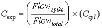
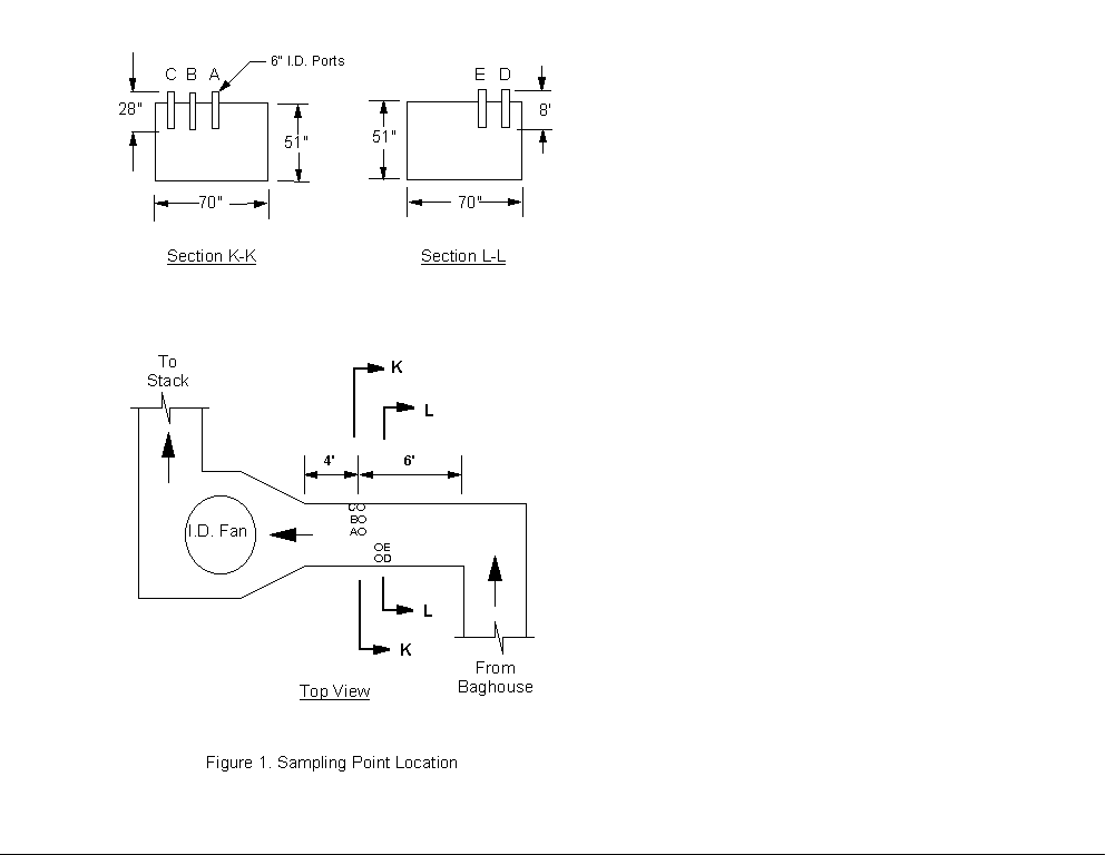
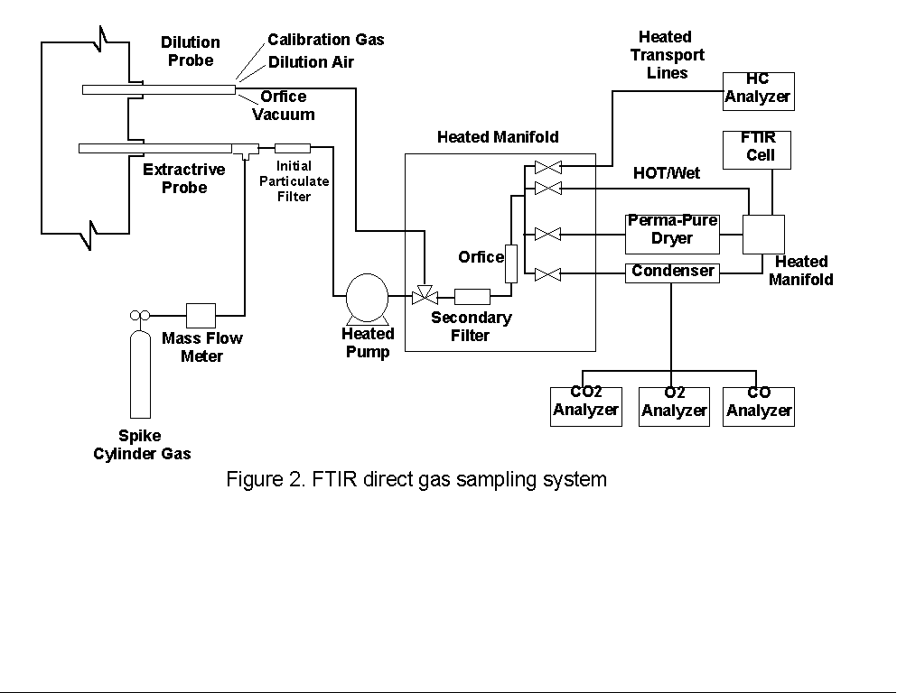
2.0 PROCESS DESCRIPTION AND SAMPLE POINT LOCATIONS2.1 PROCESS DESCRIPTIONThe test facility consists of five boilers. Testing was performed on Unit 2, which is a bituminous coal-fired boiler with an approximate heat input of 68 MBtu/hr. Bituminous coal is pulverized and blown into the combustion chamber by fans, providing simultaneous fuel suspension and combustion. The combustion gases and particulate exiting the boiler pass through an air preheater, baghouse, and an induced draft (I.D.) fan before being exhausted to the atmosphere via a stack (see Figure 1). Measurements during this screening test were made on the outlet location of the Unit 2 baghouse. Direct gas extraction testing employed 30.5 meters (100 feet) of heated sample line to connect the sampling probe to the heated manifold in the FTIR truck (see Section 3.1). Concentrated samples were obtained at the sampling port locations (see Section 3.2). 2.2 BAGHOUSE OUTLET SAMPLE POINT LOCATIONFive 6-inch diameter sample ports were available at the outlet of the baghouse, a location that is approximately 1.2 meters upstream of the I.D. fan. The ports were equally spaced along a 1.9 meter wide section of the duct that was approximately 1.9 meters deep. Access to this location was provided by stairs and a catwalk. Each probe sampled effluent at a point near the center of the duct. Electric power was available at a level below the sample point location (approximately 7.5 meters). The average temperature of the flue gas was approximately 160 deg C (320 deg F). Direct gas phase extraction and sample concentration samples were taken from ports E and A, respectively. Flow measurements were conducted daily using all the available ports. 3.0 EMISSION TEST SYSTEM DESCRIPTIONTwo different experimental techniques were employed. The first, referred to as direct gas extraction, introduced the gas stream to the sample manifold in the mobile unit from where it could be sent to the infrared cell. It is expected that direct gas extraction provides a representative sample by maintaining gas composition. A second technique, referred to as sample concentration, passed a known volume of gas through an absorbing material packed into a U-shaped stainless steel collection tube. After sampling was completed, the tube was then heated and any collected compounds were desorbed into the FTIR cell and diluted with nitrogen to one atmosphere total pressure. With this technique, concentrations of species detected in the absorption cell are generally higher than their concentrations in the effluent so that it is possible to achieve lower detection limits for some HAP's. Any lowering of the detection limit depends on the volume of gas sampled and efficiency with which a particular compound will adhere to, and desorb from, the sorbent. Validation tests of the FTIR technique were conducted using both the extractive gas phase system and the auxiliary sample concentration system. Infrared absorbance spectra of the gas streams from the outlet of the baghouse (see Section 2.0) were recorded and analyzed. Components of the emission test systems prepared by Entropy for this testing are described below. 3.1 DIRECT GAS EXTRACTIONAn extractive system was used to transport the gas stream to the FTIR spectrometer in the gaseous phase (see Figure 2). 3.1.1 Sampling System and ProceduresGas was extracted through an 8-foot heated stainless steel probe. A heated Balston particulate filter rated at 1 micron was installed at the outlet of the sample probe. A 30.5 meter (100 foot) section of heated 3/8- inch O.D. Teflon® sample line connected the probe to the heated sample pump located inside the mobile laboratory. The temperature of the sampling system components was maintained at approximately 150 deg C. All components were constructed of Type 316 stainless steel, glass, or Teflon®. Digital temperature controllers were used to control and monitor the temperature of the transport lines. All points of connection were wrapped with electric heat tape and insulated to ensure that there were no "cold spots" in the sampling system where condensation might occur. The sample pump provided approximately 12 to 16 L/min of sample gas flow, depending upon sample line length and flue gas conditions at the sampling location. The heated sample flow manifold, located in the FTIR truck, included a secondary particulate filter and valves that allowed the operator to send the sample gas directly to the absorption cell or through one of the gas conditioning systems. The extracted gas sample was treated in one of two ways. Sample sent directly to the FTIR cell was considered unconditioned, or "hot/wet." This sample is more representative of the actual effluent composition than any type of intentionally conditioned sample. The gas stream could also be directed through a condenser to remove most of the water. The condenser employed a standard Peltier dryer to cool the gas stream to approximately 3 deg C. The resulting condensate was collected in two traps and removed from the conditioning system with peristaltic pumps. This technique is known to leave the concentrations of inorganic and highly volatile compounds very near to the stack concentrations (dry-basis). The condenser was tested in an effort to ascertain which HAP's can be reliably quantified using this system. Time constraints precluded testing of the dilution and Perma-Pure systems shown in Figure 2). 3.1.2 Analytical System and ProceduresThe FTIR equipment employed in this test consisted of a refractive scanning interferometer, a heated infrared absorption cell, a liquid nitrogen cooled mercury cadmium telluride (MCT) broad band infrared detector, and a computer. The interferometer, detector, and computer were purchased from KVB/Analect, Inc., and comprise their base Model RFX-40 system. The nominal spectral resolution of the system is one wavenumber (1 cm-1). Sample was contained in a variable path white cell, model 5-22 H, manufactured by Infrared Analysis, Inc. Heated jackets and temperature controllers were used to maintain a cell temperature of 115 deg C (240 deg F). The absorption path length was externally adjustable from 2.2 to 24.2 meters. For the validation, a path length of 22 meters was used. The pathlength was determined by visual inspection of the number of optical passes of the infrared radiation within the cell, using a co-linear white light source mounted at the interferometer output flange. The pathlength was verified by inspection of a 100 ppm ethylene calibration transfer standard (CTS) gas and comparisons with similar spectra recorded along with the reference spectra used in the quantitative analysis (see also Section 4.3). Additional details regarding the testing and analytical procedures are found in Sections 4 and 5. Standard gas analyzers were operated to provide dry basis concentration measurements of oxygen (O2), carbon monoxide (CO), and carbon dioxide (CO2) from a portion of the condenser sample stream, which was split of at the condenser outlet. The O2 content of the gas stream was determined using a Teledyne Model 320P-4 analyzer with a patented micro-fuel cell. A Thermo Environmental Instruments Model 48 CO analyzer employing gas filter correlation (GFC) was used to measure CO by infrared (IR) absorption. To measure the CO2 concentrations, a Fuji Model 3300 CO2 non-dispersive infrared (NDIR) analyzer was used. A Ratfisch Model RS255CA was employed to measure the total hydrocarbon content in the "hot/wet" stream, a portion of which was split off at the outlet of the heated manifold for this purpose. All the analyzers were calibrated at the beginning and end of each test period using EPA Protocol 1 certified gas blends. Propane in air was used to calibrate the Ratfisch instrument. Measurements provided by the analyzers were averaged over the time periods when direct gas extraction sampling was conducted. Sample concentration sampling was conducted concurrently with direct gas extraction testing. 3.2 SAMPLE CONCENTRATIONSample concentration was performed using the adsorption/thermal desorption technique described immediately below in Sections 3.2.1 and 3.2.2. Four gas samples were collected simultaneously during sample concentration each run using a quadruplicate ("quad-") train assembly. A single sampling train is depicted in Figure 3). 3.2.1 Sampling System and ProceduresComponents of a single sampling train include a heated stainless steel probe, heated filter and glass casing, heated Teflon® connecting line, an optional stainless steel air-cooled condenser coil, stainless steel adsorbent trap in an ice bath, two water-filled impingers followed by an empty knock-out impinger, an impinger filled with silica gel, a sample pump, and a dry gas meter. The air-cooled condenser coil was found to be unnecessary during this test, and was not employed. All heated components were kept at a temperature above 120 deg C to ensure no condensation of water vapor within the system. The sorbent trap was a specially designed stainless steel U-shaped collection tube filled with 10 grams of Teflon® sorbent and plugged at both ends with glass wool. Stainless steel was used for the construction of the adsorbent tubes because it gives a more uniform and more efficient heat transfer than glass; this is an important consideration, since maintenance of the Teflon® temperature is important during both the sampling and thermal desorption steps of the technique. Sampling was conducted at approximately 3.1 to 4.2 liters per minute (0.10 to 0.15 standard cubic feet per minute for collection times of approximately 90 minutes. The sampling rate was close to the maximum that could be achieved with the sampling system and the collection time was chosen to provide a total sampled gas volume of 280 liters (10 standard cubic feet). Sampling a larger volume is possible, but the time required would have been prohibitive for this test. The spike gas flow rate, controlled by a needle valve upstream of the mass flow meter, was chosen to provide concentrations of approximately 500 ppb, for each spike compound, in the front half of the heated filter. Exact spike loadings were calculated from the constant spike flow rate and other parameters described in Section 5.1. Prior to and following performance of the tests, the mass flow meters were calibrated against standard dry gas meters at various flow rates, ambient temperatures, and delivery pressures. These devices were found to be extremely accurate ( +_ 1% total integrated flow) and stable under all conditions. Before the Teflon® adsorbent packed in the sample tubes was used, the following cleaning procedures were employed to remove any impurities that might desorb along with the sample compounds collected. The packed tube was heated to 350 deg C while being purged with preheated nitrogen at 1 to 2 lpm. The heating and nitrogen flow were maintained for up to 18 hours. Cleaning the desorption tubes resulted in a decrease in impurity-related bands that Entropy has observed in spectra from the desorption of new, commercially precleaned Teflon®. However, contaminants from other sources did affect the test procedures and results, as described in Section 6.4.4. 3.2.2 Analytical System and ProceduresAfter each sample was collected, condensed water was removed from the sample tube. This was accomplished by immersing the tube in an ice bath and purging it with dry nitrogen for eight minutes. The compounds collected on the Teflon® were then recovered and analyzed as follows. Each tube was separately wrapped with heat tape and placed in a heating chamber. One end of the sample tube was connected to a line leading to the inlet of the evacuated FTIR absorption cell. Gas samples were desorbed from the Teflon® by heating the tube to 250 deg C, then purging the tube contents into the FTIR absorption cell with a preheated stream of UPC grade nitrogen gas. The purge was continued until the cell pressure reached one atmosphere, which required 8.5 liters of nitrogen. The infrared absorption spectrum of the desorbed gas was then recorded. The cell was then evacuated, and the purging process was repeated. The infrared spectrum of the gas resulting from the second purge was examined to verify that no infrared-absorbing compounds remained on the Teflon® after the first purge. Additional details regarding the testing and analytical procedures are found in Section 4 and Section 5. 4.0 TESTING PROCEDURESAt the baghouse outlet location described in Section 2.0, some or all of the following testing procedures were performed. The duration and exact nature of each procedure depended on the characteristics of the gas stream and the observed equipment performance. 4.1 SET UP PROCEDURESThe gas phase extractive probe and/or quad-train assembly was installed at the baghouse outlet sampling location. Temperature and leak checks of all sampling, conditioning, and FTIR analytical systems were performed. The CO, CO2, O2, and hydrocarbon analyzers were calibrated according to standard EPA test procedures using EPA Protocol 1 calibration gases and procedures similar to those described in EPA Methods 3A, 10, and 25A. The FTIR system was prepared at 22 meter path length. Flue gas volumetric flow rate was determined prior to each testing run according to an EPA Method 2 traverse and the diluent measurement data provided by the CO2 and O2 analyzers. Pitot tube traverses were performed periodically at one port location and compared to the Method 2 data. No significant variation of the flow was observed over the test period. 4.2 SAMPLING PROCEDURESThe sampling and spiking procedures described below were conceived to allow cost-effective validation of the two FTIR analytical methods for as many gaseous HAP compounds as possible. Sampling methods were adapted from the Analyte Spiking procedures described in EPA Method 301, Section 5.3. Performing the described analyte spiking procedures into a gas stream requires a relatively large volume of well-characterized gas standards, which are available and practical for field use only in high pressure gas cylinders. Consultations were held with the Research Division of Scott Specialty Gases, Inc. to determine the appropriate gas mixtures. Both sample stability and spectroscopic compatibility were considered in selecting the sets of compounds to be included in each cylinder. The cylinder gases are further described and listed below in Section 4.4. Adaptations of Method 301 procedures used in this test are described below for each sampling technique. 4.2.1 Direct Gas ExtractionBecause only one complete FTIR system was available for the test, it was not possible to conduct simultaneous sampling using the direct gas extraction system. Instead, the required 24 samples (12 spiked and 12 unspiked) were collected sequentially for each of the 11 spike cylinder mixtures tested. The derived precision of the measurements provided by the technique therefore differs from that intended by Method 301, in that it contains contributions from any variation in the source emission. The criteria pollutant CEM instruments were monitored carefully during each set of runs, and indicated extremely stable plant operation over the entire test period. Nearly complete sets of "hot/wet" and condenser samples were obtained during the test. Separate extractions of flue gas were introduced to the FTIR cell approximately every five minutes. Data were collected in groups of four consecutive unspiked spectra followed by four spiked samples. Alternate groups of four samples were extracted until the complete set of 24 spectra was obtained. Collection of these 12 spiked/unspiked sample pairs required approximately 3« hours. Samples that were compared for statistical tests were separated in time by about « hour. Because of low delivery pressure and/or equipment problems encountered during the test, two cylinders were emptied before complete sets of 12 spiked/unspiked sample pair could be collected; incomplete sets of data were obtained for cylinders #7 (8 pairs) and #8 (6 pairs) spiked into the condenser system. Because of a procedural error which was not discovered until after the testing was completed, only five pairs of samples were obtained for the hot/wet system spiked with cylinder #4 compounds. 4.2.2 Sample ConcentrationEPA Method 301, without the adaptation discussed above for the direct gas extraction system, served as a basis in planning the tests of the sample concentration technique. However, because of contamination found in the first sets of samples (see Section 6.4.4), it was necessary to limit the number of spiking analytes and/or sampling runs in order to complete the testing with the available on-site time. The number of runs permitted by these constraints was less in all cases than specified by the test protocol. The schedule was adjusted during the test to provide the maximum possible amount of information on the compounds of interest, by trading off a lower number of sample runs for an increase in the number of compounds included in the test. The concentration samples were collected independently of the direct gas extraction samples. Single runs consisted of sampling 280 liters (10 ft3) of flue gas simultaneously through the four Teflon® cartridges included quad-train. It was possible to complete two and sometimes three sampling runs in a single day. The charged sample tubes were stored on ice until the desorption step was completed the same evening. Desorptions were carried out according to the procedures described in Section 3.2. 4.3 RECORDING OF INFRARED SPECTRAAs specified in the FTIR Protocol, a spectrum of a CTS gas (100 ppm ethylene in nitrogen) was recorded before and after each testing session to check the FTIR spectrometer performance. The infrared spectrum of a gaseous compound consists of characteristic patterns of lines representing a measure of fundamental structural properties, and provides a unique "fingerprint" of the absorbing compound. Band intensities vary with concentration, making it possible to use reference spectra, obtained earlier in the laboratory, to quantify any compounds detected. However, line shapes and intensities are also influenced by instrumental factors such as gas temperature, absorption pathlength, detector response, source intensity, interferometer servo performance, and choices of optical retardation and apodization functions. The CTS spectra collected at the test site were compared to spectra of the same CTS gas, collected concurrently with the quantitative reference spectra. This comparison allows the operator to detect any instrument malfunctions and, in most instances, quantitatively account for spectral differences which related to optical retardation, pathlength and temperature variations. All spectra were recorded at a nominal resolution of 1 cm-1. The absorption cell was configured to allow 40 passes of the infrared beam to traverse the cell between the entrance and exit windows. This is equivalent to a path length of 22 meters as measured by comparing the CTS spectra to some collected earlier in the laboratory at a known (shorter) path length. Absorbance spectra were each composed of two "single beam" spectra. First, a background of the evacuated cell was collected and processed. The background gave an indication of the infrared transmission characteristics of the system and the frequency dependent sensitivity of the detector. The cell was then pressurized and a sample spectrum collected. The "single beam" sample spectrum was divided point by point by the background of the evacuated cell to give a transmittance spectrum. This removed any effects resulting from wavelength dependent transmission losses through the instrumental system. The transmittance file was then converted to absorbance for use in the subsequent analyses. To provide adequate signal- to-noise (S/N), 50 sample scans were divided by a 200 scan background. A sample absorbance spectrum could be obtained in about three minutes. Repeated treatment with wet samples can degrade the transmission characteristics of the KBr cell windows. This necessitated periodic collection of a new background spectrum to ensure a good baseline. 4.4 DYNAMIC SPIKINGWithin the time and resource constraints of the test program, Entropy conducted dynamic analyte spiking according to the procedures described in the document "Protocol for FTIR Field Validation." Prior to performance of the test, the procedures described in this document were adapted from those of Method 301 to accommodate the techniques of interest, and depart from Method 301 in two basic ways. First, the spiking was performed dynamically, that is, the spike materials were added to the gas stream as it was collected. In contrast, Method 301 assumes that a collection medium is available for (static) addition of the spike compounds prior to the collection of samples. The dynamic method employed in this test meets the method 301 requirement that the spike be introduced as close as possible to the probe tip, and is more convincing than the static method in that most elements of the sampling system apparatus are simultaneously exposed to the spike materials and stack gas over the same period of time. Second, the direct gas extraction samples were obtained sequentially (rather than simultaneously), since only one complete FTIR system (rather than the four required for simultaneous spiking) was available for the test. As discussed above, the derived precision of the technique therefore contains contributions from any variation in the source emission levels which occur during performance of the spiking procedures. Cylinder gas standards, each containing up to five HAP's at concentrations of 50 ppm (in nitrogen) were prepared for Entropy by Scott Specialty Gases. See Table 4-1 for a listing of the compounds in each cylinder, which were grouped according to vapor pressure, stability, and spectroscopic compatibility. Note that many HAP compounds cannot be stabilized in cylinders at useful (greater that 300 psig) delivery pressures, and were therefore excluded from this test. A "tracer" of 1 ppm sulfur hexafluoride (SF6) was also included in each cylinder, and was used to verify the spike compound concentrations in the direct gas extraction samples (see Section 4.4.1). 4.4.1 Direct Gas ExtractionThe components used to deliver the spike gas to the direct gas extraction sampling system were a mass flow meter and heated Teflon® line. The mass flow meter provided a measure of spike gas flow to the sampling system. The heated Teflon® line was used to heat the cylinder gas to approximately the flue gas sample temperature to avoid condensing water vapor in the sample gas. The heated spike gas was introduced to the sampling system at a "tee" located between the sample probe outlet and inlet to the Balston filter (see Figure 2) in Section 3.1.1). From this point, the spike and sample gas mixture were transported through the remaining portions of the sampling system described in Section 3.1. An orifice located at the outlet of the secondary particulate filter within the heated manifold inside the FTIR truck provided a known total flow of the sample. A spike dilution factor of five was achieved by maintaining the spike flow at the mass flow meter at exactly one quarter of the total flow. Spike flow ratios were verified in two ways. First, CTS gas (100 ppm ethylene in nitrogen) was introduced through the mass flow meter and spike line to the gas sampling system. This was done prior to insertion of the probe in the sample port so that the CTS spike was mixed with ambient air. Standard analysis programs (similar to those described in Section 5) were used in the field to determine the concentration of ethylene in the resulting sample, and in all cases verified the flow-determined dilution ratio to within five percent. Another method of verification was also employed in the field, in which spectra of the spiked samples were periodically analyzed for the concentration of SF6. The diluted SF6 tracer contained in each spiked sample was shown in every case to be the expected 0.200 +_ 0.020 ppm. 4.4.2 Concentrated SamplesSpike gases were introduced to the appropriate sample concentration trains through mass flow meters. The measured flow of gas was passed through a pre-heater coil and then introduced to the sample system at the inlet to the Method 5 particulate filter. The combined stream travelled through the cooled collection tube where compounds could be adsorbed onto the Teflon®. The total gas flow was measured with the dry gas meter. Spiking rates were chosen to provide gas concentrations of concentrations of approximately 500 ppb in the adsorbed, and yielded post-desorption concentrations of approximately 20 ppm in the FTIR cell (for compounds with high adsorption and desorption efficiencies). Highly volatile pollutants such as the SF6 tracer gas do not adsorb well on Teflon®, and this compound was not detected in the concentrated, desorbed samples. Consequently, the SF6 tracer could not be used to provide a check of the spiking rate (as described above for the direct gas extraction tests). The expected spike concentrations for these samples were derived from the standard concentrations, flow meter readings, spike gas flow time, and total sample gas volumes (see Section 5.1.2). 5.0 ANALYSIS PROCEDURESThe goals of the field test described here are the characterization of bias, precision, and range of the FTIR technique in conjunction with three sampling systems. EPA Method 301, which allows the use of spiking or comparisons to a validated test method, was taken as the basis for calculation of these quantities; it specifies the comparison of analytical results for samples containing a known amount of spike material to the results for samples containing no spike material. The spiking procedures and associated statistical treatment of the analytical results via Method 301 replace several of the calculational methods prescribed in the FTIR Protocol. Some departures from the standard Method 301 testing procedures were adopted for this test, mainly because the requirement of simultaneous, quadruplicate sample collection is impractical for the direct gas extraction method. A sequential testing procedure, in which source variations are subsumed in the method's derived precision, was adopted as an alternative for this test. The procedures are described in a document entitled "Protocol for FTIR Field Validation," which was developed by Entropy and submitted to EMB with the site specific test plan for this test. When Method 301 is not employed, recommended alternate methods for FTIR analysis of stack effluent are described in detail in the "Protocol for Applying FTIR Spectrometry in Emission Testing" (hereafter, the "FTIR Protocol"), which was developed by Entropy under EPA contract. The procedures of the FTIR Protocol were employed to generate and characterize the sample and reference spectra on which the quantitative spectral analyses are based; these characterizations are described in detail above and in reports previously submitted to EMB by Entropy. Most other data analysis procedures of the FTIR Protocol are intended to provide estimates of measurement uncertainties from various instrumental and analytical effects. An example of such an quantity is the "Fractional Reproducibility Uncertainty" (FCU), which provides a measure of the analytical uncertainty related to the reproducibility of the spectral data through repeated application of a "calibration transfer standard" gas. Because the calculations performed in this work are based on the final HAP concentrations, this and other errors are included in the statistically determined measurement uncertainties required by Method 301 (see Section 5.3.1), and are not addressed in this report. 5.1 CALCULATION OF EXPECTED SPIKE COMPOUND CONCENTRATIONSAs described in Section 4.0, cylinders containing known concentrations (approximately 50 ppm in all cases) of HAP compounds in nitrogen were introduced into one half of the samples to be analyzed. It should be noted that no spectroscopic evidence of any of the spike compounds was found in the samples which were unspiked. The expected concentration for all HAP's in unspiked samples was accordingly taken as zero for the purposes of the statistical calculations prescribed in Method 301. Implications of this procedure are addressed in Sections 5.0 and 6.0. 5.1.1 Expected Concentrations in Spiked Gas Phase SamplesExpected concentrations of HAP spike materials in gas phase samples were calculated on the basis of flow rates measured during the field test. These flow rates were constantly maintained during the performance of the field testing for each HAP spiking group, and were verified to within +_ 10% by spectroscopic analysis for the 1 ppm SF6 tracer gas component in each cylinder. The value for the expected concentration from the gas phase sampling is given by
where: Cexp is the expected gas spike concentration. Flowspike is the measured flow rate for the spike gas. Flowtotal is the measured flow rate for the spike gas plus the stack gas. Ccyl is the cylinder concentration of the spike compound. 5.1.2 Expected Concentrations in Spiked, Concentrated SamplesExpected concentrations of HAP spike materials in concentrated samples were calculated on the basis of spike flow rates and total gas sample volumes measured during each run of the field test. These quantities were not always the same for each run involving a spiking compound group, and also varied for the two spiked sampling trains within each run. To allow use of the Method 301 statistical tests, it was necessary introduce scaling factors designed to yield equal expected concentrations for all the trains and runs. These factors were taken into account in corrections to the observed spike concentrations (see Section 5.2.3). The expected concentration in the sample concentration system is calculated in two steps. The first equation determines the amount of spike gas that is placed on the Teflon®. It is given by
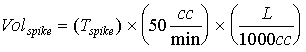
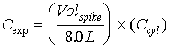
where: Volspike is the volume (in liters) of the spike gas flowed through the sampling system. Tspike is the length of time for sampling. The value of 50 cc/min was the spike gas flow rate into the sample concentration system. The expected concentration is then given by
where: Cexp is the expected concentration. Ccyl is the cylinder concentration of the spike gas. 8.0 liters is the volume of the FTIR cell. 5.2 CALCULATION OF OBSERVED SPIKE COMPOUND CONCENTRATIONSThe reported values were calculated using the Multicomp program (Version 6), which is part of the KVB/Analect FX-70 software package. This program utilizes a calibration matrix created from a set of reference spectra. The program was employed to characterize the relation between known and calculated absorbance values of the reference spectra via least squares methods. The resulting matrix was then used to determine concentrations in the unknown mixtures. 5.2.1 Description of K-Matrix AnalysesK-type calibration matrices were used to relate absorbance to concentration. Several descriptions of this analytical technique can be found in the literature[2.]. The discussion presented here follows that of Haaland, Easterling, and Vopicka[3.]. For a set of m absorbance reference spectra of q different compounds over n data points (corresponding to the discrete infrared wavenumber positions chosen as the analytical region) at a fixed absorption pathlength b, Beer's law can be written in matrix form as
where: A is the n x m matrix representing the absorbance values of the m reference spectra over the n wavenumber positions, containing contributions from all or some of the q components; K is the n by q matrix representing the relationship between absorbance and concentration for the compounds in the wavenumber region(s) of interest, as represented in the reference spectra. The matrix element Knq = banq, where anq is the absorptivity of the qth compound at the nth wavenumber position; C is the q x m matrix containing the concentrations of the q compounds in the m reference spectra; E is the n x m matrix representing the random "errors" in Beer's law for the analysis; these errors are not actually due to a failure of Beer's law, but actually arise from factors such as misrepresentation (instrumental distortion) of the absorbance values of the reference spectra, or inaccuracies in the reference spectrum concentrations. The quantity which is sought in the design of this analysis is the matrix K, since if an approximation to this matrix, denoted by K, can be found, the concentrations in a sample spectrum can also be estimated. Using the vector A* to represent the n measured absorbance values of a sample spectrum over the wavenumber region(s) of interest, and the vector C to represent the j estimated concentrations of the compounds comprising the sample, C can be calculated from A* and K from the relation
Here the superscript t represents the transpose of the indicated matrix, and the superscript -1 represents the matrix inverse. The standard method for obtaining the best estimate K is to minimize the square of the error terms represented by the matrix E. The equation
represents the estimate K which minimizes the analysis error. Reference spectra for the K-matrix concentration determinations were de-resolved to 1.0 cm-1 resolution from existing 0.25 cm-1 resolution reference spectra. This was accomplished by truncating and re-apodizing the interferograms of single beam reference spectra and the corresponding background interferograms. The processed single beam spectra were recombined and converted to absorbance (see Section 4.3). 5.2.2 Preparation of Analysis ProgramsTo provide accurate quantitative results, K-matrix input must include absorbance values from a set of reference spectra which, added together, qualitatively resemble the appearance of the sample spectra. For this reason, all of the Multicomp analysis files included spectra representing interferant species and criteria pollutants present in the flue gas in addition to de-resolved reference spectra of HAP's used for analyte spiking experiments. A number of factors affect the detection and analysis of a spiked analyte in the stack gas matrix. One factor is the composition of the stack gas. The major spectral interferants in the coal-fired boiler effluent are water and CO2. At CO2 concentrations of about 10 percent and higher, weak absorption bands that are normally not visible begin to emerge. Some portions of the FTIR spectrum are not available for analysis because of extreme absorbance levels of water and CO2, but most compounds exhibit at least one absorbance band that is suitable for analysis. A second factor affecting the analysis is the number of analytes that are to be detected. The gas cylinder spiking mixtures were prepared with 3 to 5 compounds each so that spectrum would not become overly complicated. Even so, this means that a spiked sample contained up to 13 compounds including HAP's, interferant species, and criteria pollutants that were present in the flue gas. A set of Multicomp program files was prepared for each of 11 cylinder mixtures with a separate file for quantifying each compound (47 files total). Four baseline subtraction points are specified for each analytical region, identifying an upper and a lower baseline averaging range. The absorbance data in each range were averaged, a straight baseline was calculated through the range midpoint using the average absorbance values, and the baseline was subtracted from the data prior to K-matrix analysis. Within a cylinder group, all of the files contained the same set of reference spectra, which represented the compounds listed under each group. Program files within a grouping differed only by the analytical region(s) and baseline subtraction techniques specified in the file input. In addition, every file used for gas phase analysis contained spectra of sulfur dioxide (SO2), carbon dioxide (CO2, 10 to 15 percent), water (approximately 5 percent by volume), and carbon monoxide (CO). It was also necessary to include nitric oxide (NO) and nitrogen dioxide (NO2) in some of the files. NO was not, in general, an important spectral interferant, but in cases where the analytical region included frequencies near 2900 cm-1 it was necessary to account for NO2, especially in spectra of condenser samples. The sample concentration spectra contained water and small amounts of CO2. In addition to the interferants mentioned, hydrogen chloride (HCl) was present in the stack matrix. Concentrations of interferant species remained relatively constant during the testing, but the concentration of HCl varied by as much as 70 percent below its maximum concentration. Prior to the actual field test, synthetic spectra were prepared using sample spectra that had been obtained during previous testing at a coal- fired boiler. K-matrix programs were then constructed which could adequately analyze the synthetic spectra. These analysis programs were found to serve as a useful starting point; all the finalized Multicomp routines are based on the programs prepared using the synthetic spectra. Preparation of the synthetic spectra proceeded in the following stages. First, Entropy obtained a 1 cm-1 reference spectrum of each cylinder mixture to be used in the analyte spiking experiments. Second, the cylinder spectra were scaled by a factor of 0.2 to simulate the anticipated dilution. Finally, a computer generated synthetic spectrum was created by adding a scaled cylinder spectrum to each of several sample spectra from the coal-fired boiler. This resulted in a set of synthetic spectra (for both "hot/wet" and condenser samples) representing simulated spiked samples in a stack matrix similar to what would be encountered during the validation testing. 5.2.3 Concentration Correction FactorsCalculated concentrations in sample spectra were corrected for differences in absorption pathlength between the reference and sample spectra according to the following relation:
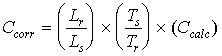
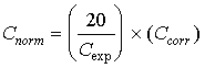
where Ccorr is the pathlength corrected concentration. Ccalc is the initial calculated concentration (output of the Multicomp program designed for the compound) Lr is the pathlength (3m) associated with the reference spectra. Ls is the pathlength (22m) associated with the sample spectra. Ts is the absolute temperature of the sample gas (388 deg K). Tr is the absolute gas temperature at which reference spectra were recorded (300 to 373 deg K). In addition to the pathlength and temperature corrections, the sample concentration values were corrected for the different expected concentrations. This adjustment was due to the different amounts of spike gas that were applied to the sample concentration system. All of the expected values were normalized to values of 20 ppm; in addition, all of the calculated concentration values were also normalized in the same manner as the expected values. The normalization factor is given by
where Cnorm is the normalized calculated concentration value. Cexp is the expected concentration of the spike compound. Ccorr is the pathlength adjusted value that was determined previously. Corrections for variation in sample pressure were considered, and found to affect the indicated HAP concentrations by no more that one to two percent. Since this is a small effect in comparison to other sources of analytical error identified in this study, no sample pressure corrections were made. The term "observed concentration" is used hereafter to indicate either the corrected concentration Ccorr (in the case of direct gas extraction measurements) or the normalized concentration Cnorm (in the case of concentrated sample measurements). 5.3 COMPARISONS OF EXPECTED AND OBSERVED SPIKED COMPOUND CONCENTRATIONSDuring collection of both the concentrated and direct gas extraction samples, the analyte spiking validation procedures specified in EPA Method 301, Section 6.3 were followed as closely as possible. According to Method 301, half of the samples must be spiked and the other half remain unspiked. The precision and the bias of the measurement system are calculated via statistical comparisons these spiked and unspiked data. 5.3.1 PrecisionThe precision of the measurement system (sampling and analytical) is measured as the relative standard deviation (RSD) presented as a percentage. The RSD determines the "size" of the sample standard deviation relative to the sample mean. The RSD was calculated for both the spiked and unspiked samples using the following procedures: a. The differences, di, between the observed and expected concentrations of the spiked pairs ("spiked differences") and the unspiked pairs ("unspiked differences") were calculated separately. Then the standard deviations of the spiked differences and unspiked differences were formed using the following equations:
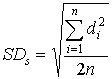
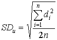
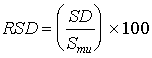
where: SDs = standard deviation of the spiked differences SDu = standard deviation of the unspiked differences n = number of paired samples b. The relative standard deviation was determined as follows:
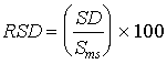
where: Sms = mean of the observed spiked sample concentrations Smu = mean of the observed unspiked sample concentrations If the RSD is less than or equal to 50 percent for both the spiked and unspiked samples, the precision was considered acceptable. 5.3.2 BiasThe bias is a measure of the systematic error inherent in the measurement system. The bias is the difference between the observed spiked value and the expected spiked value, including the difference from zero as measured by the unspiked value. Ideally, this difference will be zero. The bias was calculated as follows:
where: B = bias at the spike level Sm = mean of the observed spiked sample concentrations Mm = mean of the observed unspiked sample concentrations CS = expected value of the spiked concentration. Even if the bias is not zero, it may not be significantly different from zero. Statistical significance of the bias is determined by conducting a small sample hypothesis test of Ho: the bias is zero vs Ha: the bias is not zero, where Ho is the null hypothesis and Ha is the alternative hypothesis. A small sample test statistic, t, is calculated from the data and compared to the tabulated t value which comprises the lower limit of the rejection region for Ho at the 95% confidence level. If the calculated t statistic falls within the rejection region, the bias is statistically significant and a correction factor must be used for future testing. The statistical significance of the bias was determined as follows: 1. The standard deviation of the mean is calculated as follows:
2. The t-statistic was determined by:
The bias is considered significant if the t-statistic is greater than the critical value of the two-sided tdistribution at the 95 percent confidence level and n-1 degrees of freedom. If the bias is statistically significant, a correction factor (CF) must be calculated as follows:
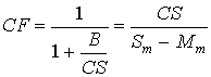
For the method to be acceptable, CF must be between 0.70 and 1.30. 6.0 RESULTS AND DISCUSSIONThe spectral analysis programs (Section 5.2.2) were applied to all sample spectra, and the resulting concentration values were corrected (Section 5.2.3). All spectra were visually compared to spectra of the spike cylinder gases to ensure that the resulting concentrations were physically reasonable and that no obvious spectral interferants had been omitted from the analytical programs. Statistical analysis of the data was carried out (Section 5.3), and compounds were classified as "validated" if they met the following criteria:
Spectra and analytical programs involving compounds for which the above criteria were not immediately met were subject to further scrutiny. In many cases, improvements in the analytical results were achieved by adjustment of the spectral region and/or baseline subtraction technique employed in the Multicomp program. Following these adjustments, the statistical analysis was repeated. Many compounds which did not initially pass the specified tests were re-classified as "validated" following such correction of the programs. For clarity, all tables associated with and described in this section have been placed at the end of this report (following Section 8.0). 6.1 COMPOUNDS WHICH MEET VALIDATION CRITERIAThe following sections present results and analytical details concerning those compounds for which the statistical data quality criteria listed above were met, for each of the three sampling systems investigated. Tables 6-1 and 6-2 summarize the compound/sampling pairs for which valid analytical programs could be devised, for the hot/wet, condenser, and concentrated samples. The number of samples is not always the 24 required by Method 301, but is sometimes lower because of procedural difficulties or time and material constraints (see Section 6.4.3). However, the statistical tests were carried out taking the number of samples into account. Several compounds (notably numbers 159 and 165 in the hot/wet samples) exhibit mean unspiked values which vary significantly from zero, but still meet the Method 301 criteria for analyte spiking. This is because the difference between the spiked and unspiked concentrations, rather than their absolute values, are used in all the statistical tests. Analytically, this effect is due slight errors in the choice of points used for baseline subtraction in the Multicomp programs. The statistical results indicate that the results of the programs are accurate when corrected for these offsets, and that the offsets could be removed by adjustment of the baseline subtraction routines. These testing procedures for these compounds are listed as having met the Method 301 criteria, but are not counted as "valid" in the totals presented in Section 7.0 Tables 6-3, 6-4, and 6-5 present detailed analytical results for each compound in the hot/wet samples, condenser samples, and concentrated samples, respectively. Each entry in these Tables provides the observed concentrations for the spiked and unspiked samples and the statistical quantities defined in Section 5.3. Tables 6-6a, 6-6b, and 6-6c present the reference spectral files, associated concentrations, analytical regions, and baseline correction details for the Multicomp programs employed in the calculation of the observed concentration of the indicated compound in each type of sample. Each page of the Table pertains to a particular compound/sampling system combination, and appears in the same order as the information of Tables 6-3, 6-4, and 6-5. 6.2 COMPOUNDS WHICH DO NOT MEET VALIDATION CRITERIATables 6-7, 6-8, and 6-9 list the statistical details for those spike compounds for which the required data quality criteria were not met. For brevity, details of the associated Multicomp analyses are not provided in this report. 6.3 CEM AND FLOW DATAData from the CEM analyzers were compiled once per second by the associated data acquisition system, then combined to provide one-minute average values. Table 6-10 summarizes the average concentration measurements collected over each sample run period. The shaded areas within the Table represent time periods over which the sample was spiked with cylinder gases containing HAP compounds; analyzer values during these spiking periods are biased by the presence of the cylinder gas, and are therefore not presented. The CO, CO2, and O2 data are dry basis measurements because the sample provided to these analyzers was passed through the condenser system before being introduced to the instruments. Sample gas analyzed by the THC instrument bypassed the condenser; these measurements were identically zero for the entire test period, and are omitted from Table 6-10. Table 6-10 also presents the flue gas volumetric flow, which was determined for each set of cylinder gas spike runs (see Section 4.4.1). The water content and average delta p presented in the Table are the results of wet-bulb/dry-bulb measurements and velocity traverses conducted before each run. Averaged O2 and CO2 concentrations were coupled with the water and delta p values to calculate the flue gas flow rates. 6.4 DISCUSSIONSeveral generalizations may be may concerning the failure of the three sample types (hot/wet, condenser, and concentration) and/or analytical techniques to meet the Method 301 validation criteria. The discussions below identify the compounds according to their identification number, which is listed with each entry in Tables 6-1, 6-2, 6-3, 6-4, and 6-5, and in Tables 6-7, 6-8, and 6-9. 6.4.1 Spectral Interferences and Large Sampling LossesA number of compounds are simply not observable in the spectra of the direct gas samples delivered to the FTIR instrumentation. These include compounds 028, 084, 115, and 143 in the hot/wet samples, and compounds 084, 115, and 143 in the condenser samples. For these data, the calculated spiked and unspiked concentrations varied greatly from sample to sample, or differed only slightly for individual samples. These effects are probably caused by heavy spectral interference, losses in the sampling system, or a combination of both effects. The concentrated sample spectra indicate that a number of the spike compounds are not efficiently delivered to the FTIR sample cell. There are several possible reasons for this effect. Compounds with low boiling points are probably not efficiently adsorbed by the Teflon® trap, or are lost during the drying cycle; others are highly water soluble and are likely dissolved in the liquid formed in the trap, and subsequently lost in the drying process, rather than being adsorbed. Table 6-11 lists those compounds which were not detected after thermal desorption of spiked samples, along with their boiling points and solubilities in water. Table 6-12 presents the same information for those compounds which were detected. The trends noted above are clear from a comparison of these two lists of physical data. Of the compounds which were detected in concentrated samples, and for which analytical programs were devised, several (numbers 010, 159, and 169), failed to meet the Method 301 criteria because of heavy losses in the sampling system or because of heavy spectral interferences. 6.4.2 Systematic ErrorsThere is statistical evidence that some compounds are consistently delivered by the sampling systems (the RSD values for the spiked samples are low) and are not subject to extreme spectral interferences (the RSD values for the unspiked samples are low), but the analytical results are consistently low (mean spiked value less than the expected value) or too high (mean spiked value greater than the expected value). In the hot/wet system, the spiked results are consistently low for compounds 029 and 108, and the spiked results are too high for compounds 039, 046, 077, 104, 106, 112, 171, and 172. In the condenser system, the spiked results are consistently low for compounds 003, 009, 028, 029, 108, and 115, and the spiked results are too high for compounds 039, 046, 168, 172, and 192. In the concentrated samples, the spiked results are consistently low for compounds 009, 029, 108, 112, and 166, and the spiked results are too high for compounds 022 and 159. There are several possible systematic errors which could lead to such results, including (1) errors in the reference spectrum gas concentration, spike cylinder gas concentration, or both; (2) band intensity mismatch between reference spectra and sample spectra, caused by instrumental distortion or gas temperature mismatch between reference and sample spectra; and (3) a consistent loss of a certain fraction of the spike concentration in the sampling system (although this impacts only those results for which the spiked values are lower than expected). Even when the techniques fail to meet the Method 301 criteria because of these effects, they may provide useful lower concentration limits (in those cases when the observed concentration is lower than expected) or upper concentration limits (in those cases when the observed concentration is higher than expected). 6.4.3 Statistical IssuesA fundamental question is posed by the fact that several compounds failed to meet the validation criteria solely because the mean of the observed values (Smu) was close to zero, causing the RSD of the measurement to diverge and exceed the 50% limit. This effect is due only to the failure of the statistical tests when the observed unspiked concentration is nearly zero. It is well illustrated by the case of acrolein, compound number 006, when spiked into the condenser samples (although the compound did meet the validation criteria in the hot/wet samples). The average unspiked concentration was extremely close to zero for this set of measurements, with maximum deviations from zero equal to 0.69 and -0.30 ppm. However, the prescribed statistical analysis leads to an RSD value of 587% for this set of measurements, which is well outside the validation criteria. Note that if the average unspiked mean had been much greater in absolute magnitude than the actual value of 0.04 ppm, the analysis would have easily passed the RSD test. For each sampling system, a number of compounds failed to meet the Method 301 criteria solely because of this effect. They are, for the hot/wet system, compounds 075, 111, 117, 147, 151, 153, and 192; for the condenser system compounds 006, 022, 030, 104, 111, 166, and 167; and for the concentrated samples, compounds 114 and 142. Several compounds exhibited both this statistical problem and a correction factor (CF) outside the allowed range. The techniques may therefore also be suitable for determination of approximate concentrations or concentration limits (as discussed in Section 6.4.2) for several compounds. They are, in the condenser system, numbers 003, 009, and 039; in the concentrated samples, numbers 009, 022, 029, 112, and 159. The number of samples collected in this test was lower than the 24 specified by Method 301 for all the sample concentration spike compounds and several of the direct gas spikes. Portions of the Method 301 calculations provide for including the number of samples in the set, including both the calculations of the standard deviations SDs and SDu and the test for significance of the bias, which determines whether or not the correction factor need be applied for a particular compound. As the number of samples decreases from the prescribed twenty four, passing the RSD test becomes more difficult (requires higher precision of the measurements), but the bias is less often shown to be significant. 6.4.4 ContaminantsDuring the validation testing of the sample concentration method, problems were also encountered due to interference by a variety of contaminants that were collected, in addition to stack gas components and spike gas species, on the Teflon® adsorbent. During sample analysis, these contaminants were desorbed along with the desired species, and the resulting infrared spectra showed absorbances due to both the contaminants and the expected species. The presence of these contaminants in the spectra proved to be a significant impediment to determining the concentrations of the spike gas species, as well as interfering with the collection of "clean" unspiked samples. Entropy was able to identify the two most significant contaminants encountered in this study as well as their source in the sampling system. Future studies or validation tests will be able to avoid problems with these contaminants using the knowledge gained from the current work. Identification of these sources of contamination is also of importance for any workers using other sample concentration schemes, such as VOST and Semi-VOST, where similar contamination problems can potentially be experienced. The first contaminant encountered during the validation process was residual mill oil on the stainless steel probe. This contaminant, identified as a long-chain alkane hydrocarbon (CH3(CH2)nCH3, n>10) by its infrared spectrum, was observed only during the first two days of validation testing. New probes had been fabricated for this test, and the surfaces had been cleaned using solvent. It appeared this cleaning was not sufficient to remove all residual oil, in light of the high concentrations detected during the first two days of testing. The amount of oil varied considerably between the four probes used, indicating that all probes had not received equal cleaning. Validation testing utilized heated probes, and the heating process served to drive the oils off the hot metal surface and onto the Teflon® absorbent. The oil contaminant disappeared after two days, apparently because this provided sufficient time to remove all residual oil. This problem can be avoided in the future by requiring a more rigorous cleaning of new stainless steel tubing used for probes and pre-heating the probes for an extended period before use. The second contaminant was also identified by its infrared spectrum, and was determined to result from a chemical reaction[4.] involving glass wool, which was initially used in place of the standard filter in the concentration sampling system. The glass wool (Altech) was silanized, that is, treated with dimethlydichlorosilane (Si(CH3)2(Cl)2), to reduce its reactivity. The reaction product (octamethylcyclotetrasiloxane) results from a hydrolysis reaction between the water and dimethlydichlorosilane in the presence of HCl: CH3 O CH3
\ / \ /
Cl CH3 CH3 -Si Si- CH3
\ / HCl / \
4 Si + 4 H2O ------> O O + 8 HCl
/ \ \ /
Cl CH3 CH3 -Si Si- CH3
/ \ / \
CH3 O CH3
While this cyclic siloxane was definitively identified in the infrared spectra, a search of the chemical literature was required to determine the mechanism of its formation. The appended reference list cites studies that describe the reaction shown above. Note that these references are primarily from foreign (Russian and German) sources, but the abstracts have been translated and provide the necessary information to identify the reaction. This hydrolysis reaction is known to proceed under the conditions encountered in the sampling train used in the validation test. Here, the silanized glass wool was used as a filter material in the heated filter compartment between the probe and absorbent trap. Flow of hot stack gases through the filter allowed water to condense on the glass wool, and, in turn, HCl to dissolve in this condensed water. The references indicate the reaction is enhanced by the presence of dissolved HCl in the water and the elevated temperatures at which the glass wool was maintained. During the validation test, it was observed that the concentration of HCl was rather variable, and this variability seems to have also affected the concentration of the reaction product above. While the cyclic siloxane shown above is the main product, the reaction can also form a variety of other linear and cyclic siloxanes. As stated earlier, the infrared spectra clearly showed the presence of the above cyclic siloxane, which was unambiguously identified using a spectra search library on the FTIR system. The remaining unidentified contaminants are probably other products of this reaction mechanism. Entropy was able to clearly identify the cyclic siloxane and the mill oil for two reasons. First, these species have quite distinct infrared spectra that permit identification using spectral search software. Second, the concentration of the different contaminants varied considerably during the testing, and some unspiked spectra were recorded that only contained a single contaminant. Indeed, Entropy was able to use and manipulate these spectra so they could be used as "reference" spectra in the mathematical multicomponent analysis. The presence of the contaminants hampered the validation process for a number of reasons. Firstly, the mathematical analysis used to determine concentrations from an infrared spectrum (K matrix method) requires that the analyst have reference spectra for all species present in the analyzed spectral regions. Since the absorbances due to the contaminants often overlapped those of the desired analytes, and no reference spectra were available for some of the contaminants, the accuracy of the mathematical analysis was impacted. Secondly, there were a number of different contaminants (at least four) which were present simultaneously and in varying relative concentrations. It should be noted that these concentrations varied even among the four trains of the quad-train in a given sampling run. Thirdly, at times the concentration of one or more contaminants was so high that it absolutely precluded analysis of the infrared spectrum. In these cases the contaminant absorbance overwhelmed that of any other species present. The problems with sampling system contaminants experienced in the current study, and especially the identified contaminants and their sources within the sampling system, are significant for other emissions testing methods besides the sample concentration scheme utilized in the current study. Since water and HCl are commonly encountered in stack gas, and glass wool is commonly utilized in sampling systems, the reaction to form siloxanes may occur in a variety of other test methods. Likewise, contaminants like the residual mill oils on the heated probe can be present. The fact that these contaminants could be identified serves to reinforce some of the strengths of FTIR as a measurement technique. Future validation and screening tests utilizing this sample concentration technique will avoid these contamination problems by using Teflon® or other inert materials for filtration. 7.0 CONCLUSIONSThe FTIR spectrometric analytical procedures described in this report have been subject to a test for validity according to a revised form of EPA Method 301, in which the option for (dynamic) analyte spiking was chosen. On the basis of these tests and the prescribed statistical calculations, the methodology is to be considered "valid" for a number of compounds in three different sampling systems. The number of compounds considered "valid" for each sampling system, and the approximate in-stack concentration corresponding to the spike concentration level, are summarized below. 23 compounds for hot/wet sampling, at 10 ppm. 24 compounds for condenser sampling, at 10 ppm. 11 compounds for concentrated samples, at 500 ppb. With the exception of m-xylene, all compounds which met the validation criteria in concentrated samples also passed for either the hot/wet or condenser samples. 15 compounds are considered validated for both the hot/wet and condenser sampling systems. 32 different compounds are considered valid for at least one sampling system, as well as a total of 58 compound/sampling system combinations. The test procedures differed from those prescribed in Method 301 in the following ways: Gas phase samples were collected sequentially, rather than simultaneously. The required number of samples (24) was not obtained for all gas phase spike compounds, and fewer than the required number were obtained for all sample concentration spike compounds. Gas phase samples were spiked dynamically at 20% of the sample volume. The equivalent spike levels (10 ppm for gas samples, 500 ppb for concentrated samples) did not approximate the emission level in the effluent. Further testing may be warranted for extension of concentration to high-boilers (via addition of cryo-trapping), extension of gas phase sampling to particular reactive species (e.g. HCl, HF), and to compounds for which cylinder gas standards cannot be prepared. 8.0 REFERENCES1. "Method 301 - Field Validation of Pollutant Measurement Methods from Various Waste Media," Federal Register, 57(10), 988-62002, December 29, 1992. 2. "Computer-Assisted Quantitative Infrared Spectroscopy," Gregory L. McClure (ed.), ASTM Special Publication 934 (ASTM), 1987. 3. "Multivariate Least-Squares Methods Applied to the Quantitative Spectral Analysis of Multicomponent Mixtures," Applied Spectroscopy, 39(10), 73-84, 1985. 4. Cyclic Siloxane Contaminant References: "Effect of hydrochloric acid on the hydrolytic polycondensation of bifunctional organochlorosilanes with chlorotrimethylsilane." Kopylov, V. M., Agashkov, S. P., Sunkovich,G. V., and Prikhod'ko, P. L., Zh. Obshch. Khim., 61(6), 1378-83, (Russ), 1991. "Preparation of siloxanes." Lehnert, R., Porzel, A., and Ruehlmann, K., Z. Chem., 28(5), 190-2, (Ger), 1988. "Study of the effect of synthesis conditions on the degree of purity of hydrolytic hydrochloric acid-waste from the production of organosilicon products." Trokhachenkova, O. P., Zh. Prikl. Khim. (Leningrad), 59(10), 2396-9, (Russ), 1986. "Effect of hydrochloric acid on the hydrolytic copolycondensation of dimethyldichlorosilane with trimethylchlorosilane." Kopylov, V.M., Agashkow, S.P., Kireev, V.V., and Krylova, M. Ye., Vysokomol. Soedin., Ser. A, 28(7), 1465-72 (Russ), 1986. "Low viscosity, storable diorganopolysiloxanes." Hamann, H., Kroening, H., Sliwinski, S., Koehler, B., Hoche, R., Fiedler, R., and Boehm, M., East German Patent DD 217814 A1 23, 8 pp., (Ger), Jan 1985. "Hydrolysis of chlorosilanes." Hajjar, A. L. (General Electric Co., USA) German Patent Ger. Offen. DE 3244500 A1 23, 9 pp., (Ger), Jun 1983 "Hydrolytic polycondensation of dimethyldichlorosilane in concentrated hydrochloric acid." Panchenko, B.I., Gruber, V.N., and Klebanskii, A.L., Vysokomol. Soedin., Ser. A, 11(2), 438-42, (Russ), 1969. |
